Introduction
I didn’t get around to posting anything last week since I was on travel and just had a lot of peripheral tasks that took me away from getting a blog post up.
** I have not seen any commercial deployments configure additional BWPs at this time.
*** Currently, you cannot configure additional BWP using srsRAN.
**** If you are using Amarisoft Callbox, there is a helpful article in their Tech Academy.
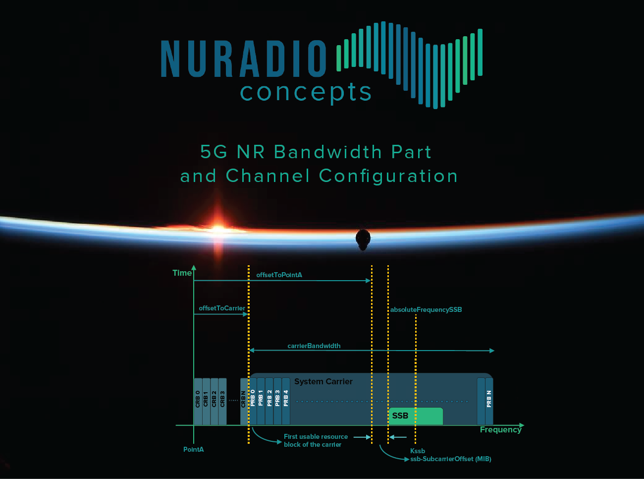
This post will be dedicated to how channels are configured in 5G NR. This is a bit more complicated with the introduction of a few different features/concepts in 5G.
- SSB: The downlink synchronization signal of a channel can be placed in many different places in the frequency domain of the carrier.
- SSB-ARFCN: Defines the center frequency of the SSB.
- GSCN: Defines the SSB-ARFCN location on the synchronization raster.
- NR-ARFCN: Defines the center frequency of the overall carrier and is defined by the channel raster.
- Bandwidth Parts: As the name implies, they are configurable parts of a carrier that can be configured with their own subcarrier spacing and bandwidth.
- Common Resource Blocks: These are resource blocks dedicated to a specific subcarrier spacing, and since each BWP can have its own SCS, there is a need for a reference point.
- PointA: Is the common reference point and refers to the center of subcarrier 0 of CRB 0.
- Physical Resource Blocks: These resource blocks belong to a bandwidth part.
There are also offsets that the UE uses to determine the location of PointA and the location of the Bandwidth Part.
- Master Information Block
- ssb-SubcarrierOffset (kssb)
- offset defined in the number of subcarriers
- (0 – 23) 15 kHz from FR1
- (0 – 11) subcarrierSpacingCommon for FR2
- subcarrierSpacingCommon
- SCS for the Common Resource Block grid
- 15 kHz or 30 kHz for FR1
- 60 kHz or 120 kHz for FR2
- ssb-SubcarrierOffset (kssb)
- System Information Block 1
- offsetToPointA
- offset defined in the number of resource blocks
- 15 Khz for FR1
- 60 kHz for FR2
- carrierBandwidth
- Defines the number of resource blocks for the channel bandwidth
- offsetToCarrier
- offset defined in number of resource blocks between pointA and subcarrier 0 within the lowest usable resource block.
- subcarrierSpacing
- the subcarrier spacing for the BWP
- locationAndBandwidth
- Resource Indication Value (RIV)
- https://www.sqimway.com/rb_calc.php (scroll down to NR RIV decoder)
- offsetToPointA

Requisite Knowledge
Subcarrier Spacing correlation to Resource Block size
Resource Block = 12 Subcarriers in frequency domain (12 SC * SCS=RB Size)
- 0: 15 kHz = 180 kHz/RB
- 1: 30 kHz = 360 kHz/RB
- 2: 60 kHz = 720 kHz/RB
- 3: 120 kHz = 1.44 MHz/RB
SSB Size
Frequency Domain = 240 Subcarriers/20 Resource Blocks
SCS Resource Block size * 20 Resource blocks = SSB Size
- 15 kHz = 3.6 MHz
- 30 kHz = 7.2 MHz
- 60 kHz = 14.4 MHz
- 120 kHz = 28.8 MHz
Channel Bandwidth vs. Usable Bandwidth
When a channel is advertised as 10 MHz, it doesn’t mean that the channel provides a full 10 MHz of bandwidth. Guard band needs to be taken into account and is not usable Bandwidth.
For example
- carrierBandwith = 52 Resource Blocks
- subcarrierSpacing = 15 kHz
15 kHz * 12 (# of Subcarriers/RB) = 180 kHz (RB Size)
180 kHz * 52 = 9.36 MHzof usable bandwidth

What is a Bandwidth Part?
Bandwidth Parts (BWP) are defined as a set of consecutive Physical Resource Blocks (PRBs) that can have their own subcarrier spacing/numerology. BWPs are configured per UE, and each UE can be configured with up to 4 BWPs in each direction. Only one can be active at a time. The motivation for BWPs is to cater to different device types that may not support the complete system bandwidth. It also allows operators to configure different SCS configurations and Bandwidths to support multiple Use Cases/Service requirements.
There are three types of BWPs
- Initial
- BWP IP = 0
- Carries the SSB and System Information
- SCS is provided by the MIB
- Other common configurations are provided by SIB1
- Default
- Fallback BWP for UE when the inactivity timer expires or UE is active on another BWP
- Downlink configuration only
- First Active
- The BWP the UE becomes active on, after receiving the RRC Message defining the BWP ID.
GSCN
GSCN is a separate raster since the SSB does not always define the center of the system carrier. It indicates the frequency position of the SSB and is used by the UE for system acquisition, and aids in reducing cell search times.

- Range of Frequencies
- SS block frequency position (SSref)
- GSCN
- Range of GSCN
- SS block frequency raster

Using the example above with the Synchronization Raster table
- SSref
- N = 527
- 527 * 1200 kHz = 632.4 MHz
- M = 3
- 3 * 50 kHz = .15 MHz
- SSref = 632.55 MHz
- N = 527
- GSCN
- 3N (3*527) = 1581
- + (M-3)/2: 3-3 = 0/2 =0
- GSCN = 1581
- SSB Block Frequency Raster
- 1.2 MHz
- Distance between last/next SSB frequency center
- 1.2 MHz
I know the graphic may be hard to read (click to view expanded media), but it shows the five configurable locations for a GSCN in the given channel configuration. You can reference the PointA calculation table in example 1 (Band n71, SSB 126510….) below.

Calculating Channel Configuration Examples


- SSB Frequency = 632.55 MHz
- SSB = 3.6 MHz/2 = 1.8 MHz
- 632.55 – 1.8 MHz = 630.75 MHz SSB Start
- SSB = 3.6 MHz/2 = 1.8 MHz
- offsetToPointA = 18
- 18*180 kHz = 3.24 MHz
- ssb-SubcarrierOffset = 6
- 8*15 kHz = .12 MHz
- 3.24+.12 = 3.36 MHz offset from SSB start to PointA
- 630.75 – 3.36 = 627.39 MHz PointA
- carrierBandwidth = 79 Resource Blocks
- 79*180 kHz = 14.22. MHz Usable Bandwidth
- 14.22/2 = 7.11 MHz
- 79*180 kHz = 14.22. MHz Usable Bandwidth
- PointA + Half of carrierBandwidth = carrier center frequency
- 627.39 + 7.11 = 634.5 MHz carrier center frequency
- NR-ARFCN 126900
If I check this with the Sqimway ARFCN Point A calculator, I get the following output. As you can see that GSCN 1581, would be the first configurable SSB location for this channel configuration. Note: Only SSBs that pass the “Coreset0 check” in the right-hand column apply to the carrier.

Ex. 2: Band n41, SSB 501870 (GSCN 6273) Bandwidth 100 MHz

- SSB Frequency = 2509.35 MHz
- SSB = 7.2 MHz/2 = 3.6 MHz
- 2509.35 – 3.6 MHz = 2505.75 MHz SSB Start
- SSB = 7.2 MHz/2 = 3.6 MHz
- offsetToPointA = 32
- 32*180 kHz = 5.76 MHz
- ssb-SubcarrierOffset = 8
- 8*15 kHz = .12 MHz
- 5.76 +.12 = 5.88 MHz offset from SSB start to PointA
- 2505.75 – 5.88 = 2499.87 MHz PointA
- carrierBandwidth = 273 Resource Blocks
- 273*360 kHz = 98.28 MHz Usable Bandwidth
- 98.28/2 = 49.14 MHz
- 273*360 kHz = 98.28 MHz Usable Bandwidth
- PointA + Half of carrierBandwidth = carrier center frequency
- 2499.87 + 49.14 = 2549.01 MHz carrier center frequency
- NR-ARFCN 509802
You can see that with having 100 MHz bandwidth, there are many more options to configure the SSB. The table below lists a portion of the SSBs.

Ex. 3: Band n78, SSB 632544 (GSCN 7838) Bandwidth 20 MHz

- SSB Frequency = 3488.16 MHz
- SSB = 7.2 MHz/2 = 3.6 MHz
- 3488.16 – 3.6 MHz = 3484.56 MHz SSB Start
- SSB = 7.2 MHz/2 = 3.6 MHz
- offsetToPointA = 24
- 24*180 kHz = 4.32 MHz
- ssb-SubcarrierOffset = 0
- 0*15 kHz = 0 MHz
- 4.32 + 0 = 4.32 MHz offset from SSB start to PointA
- 3484.56 – 4.32 = 3480.24 MHz PointA
- carrierBandwidth = 51 Resource Blocks
- 51*360 kHz = 18.36 MHz Usable Bandwidth
- 18.36/2 = 9.18 MHz
- 51*360 kHz = 18.36 MHz Usable Bandwidth
- PointA + Half of carrierBandwidth = carrier center frequency
- 3480.24 + 9.18 = 3489.42 carrier center frequency
- NR-ARFCN 632628
You can see below that this SSB is the only possible location for this particular configuration.

locationAndBandwidth
The locationAndBandwidth parameter in SIB1 is a Resource Indication Value that falls under the “initialDownlinkBWP” information element. This aids the UE, when first accessing the cell, in understanding the set of continuous resource blocks that belong to the Initial DL BWP. This value is added to the offsetToCarrier value.
Using the examples above, and the sqimway resource indicator value calculator, we can see the output for each of the carriers.
n71

n41

n78

Leave a Reply